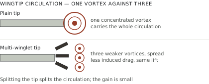
Induced drag is the price of lift. A finite wing generates a pressure difference between lower and upper surfaces, air spills around the tip from high pressure to low, and the resulting trailing vortex represents energy shed into the wake. For a transport aircraft in cruise, induced drag accounts for roughly a third of total drag; in climb it is a larger share still.
Wingtip devices attack that loss, and multi-winglets are one of several approaches to doing so.
How a winglet works
The common explanation — that a winglet blocks airflow around the tip — is wrong, and the correct explanation matters for understanding why the multiple version was proposed.
A winglet is a lifting surface operating in the flow field near the tip. Because that local flow is angled inward and upward by the developing vortex, the aerodynamic force the winglet produces is tilted forward relative to the flight direction — a component of thrust. It also alters the spanwise loading of the wing and changes how the vortex forms and rolls up.
The gain is not free. A winglet adds wetted area and therefore friction drag, adds mass, and adds a bending moment at the wing root that the structure must carry. The net benefit is a balance, and it is positive only within a range of design conditions.
The multi-winglet concept
The inspiration is the wingtip of a soaring bird. Eagles, vultures, storks and other large soaring species have separated primary feathers at the tip, splayed both vertically and in sweep. This is not incidental — it is characteristic of birds that soar at low speed with high lift coefficients, and it is absent in fast-flying species.
The aerodynamic argument is that splitting the tip into several surfaces distributes vortex formation across several weaker vortices rather than concentrating it in one strong one. Because induced drag relates to the kinetic energy in the wake, and that energy scales with vortex strength non-linearly, several weak vortices can carry less energy than one strong one of equivalent total circulation.
Each element can also be set at its own angle and dihedral, allowing the designer to tailor the loading across the tip region in a way a single surface cannot.
What the experimental work examined
Wind tunnel testing with flow diagnostics addresses questions that computation alone answers less convincingly at the time this work was done.
Force measurement across angle of attack gives the lift-to-drag ratio directly, and the comparison against a clean wing and a single winglet is the headline result.
Wake surveys — traversing a probe or using particle image velocimetry downstream — measure the velocity field and allow the vortex structure to be reconstructed. This shows whether the separate vortices actually remain separate or merge shortly downstream, which is the crux of the concept.
Flow visualisation reveals separation and interference between closely spaced elements.
The consistent finding across such studies is that multi-winglets improve lift-to-drag ratio substantially at high lift coefficients — that is, at low speed and high angle of attack — and offer little or no advantage at cruise conditions. The vortices do remain distinct for a useful distance before merging, which is the mechanism working as proposed.
Why airliners do not use them
The condition-dependence is the whole answer.
A transport aircraft spends the overwhelming majority of its flight time in cruise at a moderate lift coefficient, and the fuel burn that matters is accumulated there. A device that helps at high lift and not at cruise optimises the wrong part of the mission.
Several practical objections compound this. Multiple surfaces have more wetted area and more friction drag. Junctions between closely spaced elements generate interference drag and are prone to separation. The structure is heavier and more complex for the same root bending moment. Certification, manufacture and maintenance all cost more. And icing behaviour on multiple thin closely spaced surfaces is a genuine concern.
Where the concept fits is aircraft that operate at high lift coefficients routinely: sailplanes, some general aviation types, agricultural aircraft, and unmanned aircraft designed for endurance at low speed. These are precisely the cases where the birds’ solution and the engineering problem coincide.
The wider wingtip device family
Multi-winglets sit within a range of solutions, each favouring different conditions: the canted winglet, the blended winglet, the raked tip, the split scimitar, and the simple wingtip fence.
The persistence of variety is the informative part. If one configuration were superior outright, the industry would have converged. It has not, because the optimum depends on cruise Mach number, wing loading, span constraints at airport gates, and the structural margin available on a given airframe — and a device retrofitted to an existing wing faces different constraints from one designed with the wing.
Reading the wind tunnel results critically
Multi-winglet studies report substantial improvements, and the numbers require context before they can be compared with anything.
Reynolds number. Wind tunnel models operate at Reynolds numbers well below full scale. Boundary layer behaviour differs, and closely spaced surfaces are particularly sensitive to it — flow that remains attached at model scale may separate at full scale, or the reverse. A result obtained at low Reynolds number does not transfer to a transport aircraft without justification.
The baseline. An improvement is always relative to something. A multi-winglet configuration compared against a plain wingtip will show a large gain; compared against a well-designed single winglet, much less. Studies quoting the first comparison and studies quoting the second are not measuring the same thing, and the first is the more commonly reported.
The measured quantity. Lift-to-drag ratio at a fixed lift coefficient, maximum lift-to-drag ratio, and drag at a fixed speed are different figures of merit that can move in different directions. A configuration that improves maximum L/D may worsen cruise drag.
Whether the wing was re-optimised. Adding a tip device to an existing wing is not the same as designing wing and device together. Retrofit studies understate what an integrated design could achieve and overstate the difficulty of the comparison.
Structural and certification consequences
The aerodynamic case is only part of the engineering problem, and the remainder is where most concepts fail.
A tip device increases the bending moment at the wing root, because it adds load at the point of maximum moment arm. On an existing airframe that margin may not exist, which is why several retrofit winglet programmes required structural reinforcement that consumed much of the fuel saving in added weight.
Multiple surfaces multiply the attachment problem: each element needs its own structural path, and the junctions are stress concentrations as well as aerodynamic interference sites.
Flutter is the harder constraint. Adding mass and lifting surface outboard changes the wing’s aeroelastic behaviour, and clearing a modified wing for flutter across the flight envelope is expensive analysis and flight test. A configuration with several independently flexible surfaces is a considerably more complex aeroelastic problem than a single stiff winglet.
Certification requires demonstrating all of this, plus icing behaviour, plus lightning protection, plus maintenance access. For a large commercial programme those costs are amortisable across a fleet; for a niche application they frequently are not, which is another reason the concept has found its home in sailplanes and unmanned aircraft where the certification basis is lighter.
The biological comparison, examined properly
The bird analogy motivates the concept and it is worth stating precisely, because the loose version of it has led to overclaiming.
Slotted wingtips occur in large soaring birds and are absent in fast flyers. That distribution is the informative part: it indicates a solution suited to high lift coefficient and low speed, not a universally superior tip configuration. Falcons, swifts and other high-speed specialists have pointed, unslotted tips.
Birds also adjust their tips continuously. The degree of slotting changes with flight mode, and the feathers are individually mobile in ways no fixed structure reproduces. A bird soaring in a thermal and a bird in a glide have measurably different tip geometry.
That adaptability is the substantial part of the biological advantage, and it is exactly what a fixed multi-winglet cannot copy. Morphing structures that could are an active research area and remain heavy, complex and difficult to certify.
The honest summary is that the birds indicate the concept works under their flight conditions, which are the flight conditions of a sailplane rather than an airliner.
Where the concept is actually flying
The configurations that reached service are worth naming, because the gap between research interest and deployment is the honest measure of the idea.
Sailplanes use multiple and highly refined tip devices routinely, and competition classes have driven substantial optimisation. Several agricultural aircraft carry split tips. A number of long-endurance unmanned aircraft use multi-element tips, where the flight regime — low speed, high lift coefficient, endurance-critical — matches the concept precisely and the certification burden is far lighter.
The pattern is consistent with the aerodynamics rather than with a failure of adoption: where the mission sits at high lift coefficient, the concept is in use; where it sits at cruise, it is not.
Where the primary material sits
The experimental work sits in the aerospace engineering literature, with Georgia Tech’s aerodynamics group among the contributors on flow diagnostics for these configurations. For the underlying theory, the classical treatments of induced drag and lifting-line theory remain the necessary background, and the biological literature on avian wingtip slotting is a separate and substantial body of work that informed the concept in the first place.